Safety and legal recommendations
All rights reserved. This publication may not be reproduced, copied or stored on a memory device. Furthermore, this publication may not be used for any purpose other than as the instructions for the use of the MESI mTABLET SPO2. This publication may not be translated into other languages or converted into other formats in any way without the prior written permission of MESI, Ltd.
The contents of the instructions for use may be altered without notice. The latest version of the instructions for use is available at www.mesimedical.com/support/mtablet/instructions-for-use.
To avoid personal injury and/or damaging the device or accessories, follow the safety recommendations given below.
1.2.1 SETUP AND TECHNICAL PERSONNEL
The device must be set up by authorised personnel with adequate professional training and experience who are aware of all the dangers in relation to the setup of the device and its use and who will take adequate risk prevention measures for themselves, users, other personnel and devices.
1.2.2 ACCESS TO THE DEVICE
Only authorized persons may be given access.
1.2.3 SAFETY MEASURES
Local safety requirements are to be complied with, if so, required by regulations. If stipulated by regulations local safety requirements must be complied with. Should there be any conflict between the safety recommendations in this document and the recommendations stipulated by local regulations, the local regulations take precedence.
⚠️The MESI mTABLET SPO2 users must be adequately trained to use the device. Before the first use of the device, users must carefully read the entire instructions for use and follow the instructions for use of the connected equipment.
Product description
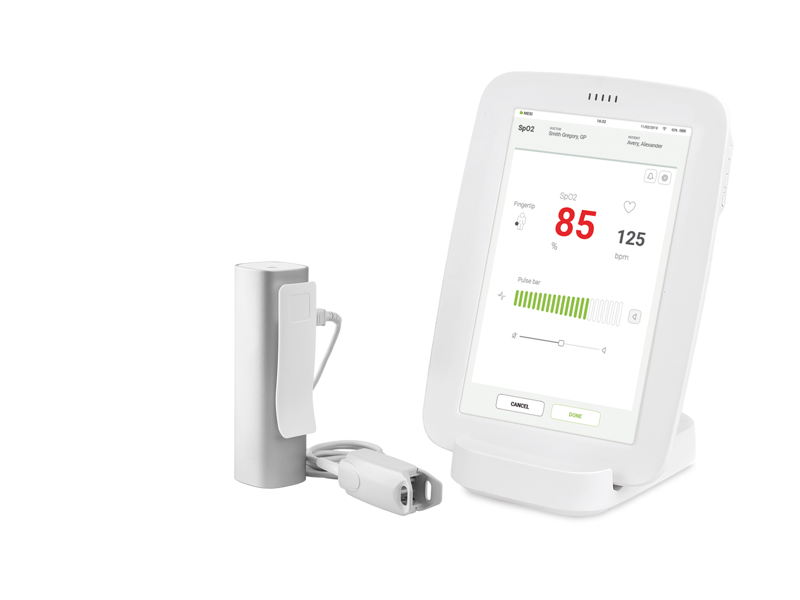
MESI SPO2 MODULE is a wireless pulse oximeter module designed for MESI mTABLET SPO2 system. The peripheral oxygen saturation and pulse rate measured on MESI PULSE OXIMETER UNIT are simultaneously displayed on the MESI mTABLET.
2.1 WHAT IS IN THE PACKAGE
The MESI SPO2 MODULE package includes the following equipment:
MESI PULSE OXIMETER UNIT (SPO2MD)
FingerClip Sensor (CS10299)
Instructions for use
MESI LARGE CHARGING PLATE – (CS4SYS; separate packaging)
MESI mTABLET (MTABMD; separate packaging)
2.1.1 ACCESSORIES
Detailed information regarding specific sensor use (patient population, body/tissue, and application) can be found in the respective sensor Instructions for Use.
NOTE: Contact your local distributor for more information about different sensors and other accessories. Use only ChipOx® compatible sensors.
⚠️Use only accessories and other parts recommended or supplied by MESI. Use of other than recommended or supplied parts may result in injury, inaccurate information and/ or damage to the unit. Follow the instructions that are provided with the specific accessory.
2.2 INTENDED USE
The MESI mTABLET SPO2 is a wireless pulse oximeter system for screening, diagnosing or monitoring acute respiratory or heart illness. System is intended for acquiring, viewing and storing measurements from adult and paediatric patients. It is a wireless system which is comprised of wireless medical tablet system, pulse oximeter diagnostic module and a 4-port charging station module.
MESI mTABLET SPO2 is intended to be used solely in a professional clinical environment by trained healthcare personnel which understand the principle of oximetry and able to place the sensor on the patient body.
MESI mTABLET SPO2 is intended to measure functional oxygen saturation of haemoglobin in arterial blood by measuring differential absorption of infrared and red light by oxygenated and deoxygenated haemoglobin. This is captured and displayed as a numerical and graphical representation on MESI mTABLET UNIT.
With the standard software, the MESI mTABLET SPO2 displays simultaneously oxygen saturation and heart rate. PRODUCT DESCRIPTION 9 The device is recharged through AC/DC power supply; however, the device is not intended to be used while connected to mains electricity.

Technical specifications
Following are the technical information regarding the MESI SPO2 MODULE, its measurement and FingerClip Sensor (CS10299) provided within the package.
3.1 MESI PULSE OXIMETER UNIT
3.1.1 DIMENSIONS
Width: 40 mm (1.57 inches)
Depth: 48 mm (1.89 inches)
Height: 135 mm (5.31 inches)
Weight: 210 g
3.1.2 POWER & BATTERY
Power & Battery| Column A | Column B |
|---|
| Battery type | Rechargeable Lithium-Polymer battery |
| Capacity | 1240 mAh |
| Examinations per battery charge | > 8000 |
| Continuous measurement | 56h |
| Charge time for depleted battery | approximately 2 hours |
3.1.3 CLASSIFICATION
Classification| Column A | Column B |
|---|
| Protection against electric shock | Class II |
| Medical device classification | Class IIa |
| Applied parts | Type BF Applied part |
| Software classification | Class B |
| RF emissions (CIPSR 11) | Group 1. Class B |
3.1.4 OPERATING CONDITIONS
OPERATING CONDITIONS| Column A | Column B |
|---|
| Temperature, operating | 10° to 40°C |
| Relative humidity | 25 to 85% (no condensation) |
| Pressure during operation | 700 to 1060 hPa |
| Ingress protection rating | IP44 |
NOTE: The device is protected against the ingress of a solid object greater than 1 mm in size as well as against the harmful effects of spraying water from all sides.
⚠️If the device is used or stored outside the specified environmental parameters, the accuracy specified within the technical specifications of the device is not guaranteed.
3.1.5 MEASUREMENT SPECIFICATIONS
Measurement specifications| Column A | Column B |
|---|
| SpO2 measurement range | 45 – 100 % |
| Pulse frequency range | 20 – 300 bpm |
| Plethysmogram | 0 – 28 LSB |
| Raw plethysmogram | 0 – 224 LSB |
| Signal quality | 0 – 100 % |
NOTE: SPO2MD is calibrated to display functional oxygen saturation.
NOTE: For compliance with ISO 80601-2-61 the temperature has been measured on each SpO2 sensor with thermocouples (Type K ≤ 0,25 mm wire) procedure. During the measurement, a functional tester FLUKE ProSim 8 with artificial finger setting was used.
Data processing: | Column A | Column B |
|---|
| Data averaging | normal and 10 % VS |
| Update period | 5 samples per second |
Alerts are implemented in MESI mTABLET UNIT and are being used for monitoring oxygen saturation and pulse rate value. It is not intended to be used for monitoring vital signs of the patient.
3.1.6 CONNECTIVITY
Data connectivity with MTABMD (Bluetooth 2.1 + EDR)
Connectivity| Receiving section | Column B |
|---|
| Frequency range | 2401.3 MHz – 2480.7 MHz |
| Bandwidth | 0.930 MHz |
Connectivity| Transmitter | Column B |
|---|
| Output power | 0.5 – 4.5 dBm |
| Frequency range | 2401.3 MHz – 2480.7 MHz |
| Modulation | GFSK |
3.2 SpO₂ SENSORS
The SPO2MD is compatible with the following SpO₂ sensors:
FingerClip 1.2 m (CS10299)
FingerClip 2.5 m (CS10299-02)
EarClip sensor (CS10109)
SoftTip® Medium (CS10318)
SoftTip® Large (CS10319)
Wrap-Sensor (CS10329)
Y-Sensor (CS10532)
The SPO2MD package includes adult FingerClip Sensor (CS10299) for SpO₂ measurement.
Provided sensor:
SpO₂ FingerClip Sensor (CS10299)
Accuracy:
The accuracy for the approved sensor according to this standard is given as the root-mean-square difference (Arms) between the measured SpO₂ values and reference SaO₂ values. SpO₂ FingerClip (CS10299): 2,3 % (Arms)
Length of the sensor:
SpO₂ FingerClip Sensor (CS10299): 120 cm
Wavelength and Output Power:
RED: 660 nm at 3,5 – 4,5 mW
IR: 905 nm at 3,5 – 4,5 mW
This information is especially useful for clinicians performing photodynamic therapy.
NOTE: For more information regarding approved sensors and other accessories see instruction manual of the sensor available in the MESI package or contact your local distributor.
Quick measuring guide
NOTE: Before using the device for the first time, read the instructions for use carefully and follow the recommendations and suggestions. This chapter only includes short instructions for the use of the MESI mTABLET SPO2. For detailed description of individual functions of the device, see chapter 5.3.1 STEP-BY-STEP SPO₂ MEASUREMENT.
⚠️The MESI mTABLET SPO2 is not intended for continuous monitoring.
4.1 PREPARATION FOR MEASUREMENT
⚠️MESI SPO2 MODULE is part of the MESI mTABLET SPO2 system. Before starting a measurement be sure that you are familiar with all devices and their instructions which are part of the system. MESI mTABLET SPO2 is comprised out of MESI mTABLET (MTABSYSW), MESI SPO2 MODULE (SPO2SYS) and MESI LARGE CHARGING PLATE (CS4SYS).
4.1.1 PAIRING WITH A MESI mTABLET UNIT
Before any measurements can be performed the MESI PULSE OXIMETER UNIT module needs to be paired to the MESI mTABLET UNIT. For detailed instructions please follow instructions in chapter 5.1.5 PAIRING.
4.1.2 CONNECTING THE SENSOR
FingerClip Sensor (CS10299) is disconnected during storage and transportation. Before first use connect the sensor to the port on the MESI PULSE OXIMETER UNIT. Ensure that the sensor is securely connected.
NOTE: MESI SPO2 MODULE comes with a FingerClip Sensor (CS10299), used for measuring SpO₂ on the finger. For instructions on other types of sensors please observe the manual supplied with the sensor package.
4.1.3 PATIENT PREPARATION
Step 1 Select the appropriate SpO₂ sensor
Select the required SpO₂ sensor depending on the patient’s category, weight and application site.
Step 2 Applying the SpO₂ sensor to the patient
Clean the application site, remove barriers (coloured nail polish, dried blood etc.) and apply the senor to the patient.
NOTE: Observe instructions for use that are provided with the pulse oximeter sensor
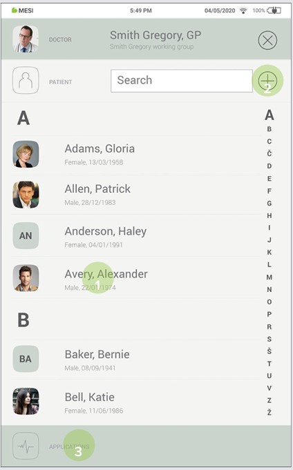
Step 1
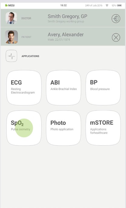
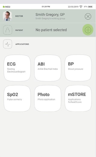
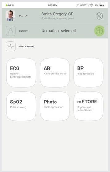
On MESI mTABLET UNIT select existing patient (1) or add a new one (2) and press the ‘‘APPLICATIONS’’ button on the bottom of the screen (3).
Step 2
On MESI mTABLET UNIT select existing patient (1) or add a new one (2).
Step 3
Apply the SpO₂ sensor to the correct application site.
NOTE: For additional information see MESI mTABLET instruction manual – chapter PATIENT MANAGEMENT.
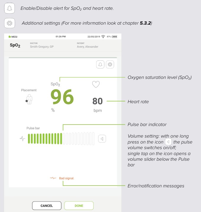
Step 4
The measuring screen displays oxygen saturation level (%), heart rate (bpm) and other settings. After selecting the patient, select the SpO₂ measurement in the application menu. After about 30s press DONE button on the bottom of the screen. MESI SPO2 MODULE provides a fast and accurate snapshot of the patient’s SpO₂ and heart rate.
4.2 RESULTS
After the measurement is complete the system will automatically switch to the result page where additional parameters of signal can be viewed by scrolling up and down. Top menu navigation provides basic actions such as:

NOTE: For more information about the result screen see chapter 5.4 REVIEWING SpO₂ MEASUREMENT.
Detailed instructions
This chapter contains all the information required by users of the device for safe, correct and accurate measurement. It includes a detailed and complete description of all the functions of the device, safety instructions and all the information required to understand the operation of the device.
5.1 FIRST TIME USE
5.1.1 BASIC FUNCTIONALITIES
MESI SPO2 MODULE package contains wireless MESI PULSE OXIMETER UNIT and FingerClip Sensor (CS10299). Before first use, the device needs to be paired with MESI mTABLET UNIT. Follow the instructions carefully.
5.1.2 ACTIVATION
When setting up the MESI SPO2 MODULE for the first time, it needs to be activated out of the shipping mode. The device will not respond until it is placed on the MESI LARGE CHARGING PLATE and a multifunctional button illuminates. It is recommended that, 5.1.2 ACTIVATION before initial use, the MESI SPO2 MODULE is fully charged.
5.1.3 TURNING ON THE MESI PULSE OXIMETER UNIT
MESI PULSE OXIMETER UNIT comes with an internal battery. Press the button on top of the MESI PULSE OXIMETER UNIT. If the green light f lashes, the module is ready for the next step. For more information on battery charging see the chapter 6.1 CHARGING THE BATTERY.
NOTE: The battery inside a completely new device is most likely not completely empty and can provide enough power to start the device up. Nonetheless, connect the device to the mains electricity using the AC/DC power supply before first use.
NOTE: When the battery needs to be replaced, the MESI mTABLET UNIT will display a battery warning. For more information see chapter 8 ERRORS.
5.1.4 AC/DC POWER SUPPLY AND BATTERY
The MESI PULSE OXIMETER UNIT uses two power sources. The mains electricity, using an AC/DC power supply for charging and battery power while performing measurement.
Connect the AC/DC power supply to a wall socket with a mains voltage of 100-240 V at 50-60 Hz and to the connector at the back of the device. The device is now recharging its battery. During this process the light on the module will be flashing orange. Only when the device is completely charged it will start flashing green. For more information see chapter 5.5 MULTIFUNCTIONAL LED BUTTON.
5.1.5 PAIRING
Before any measurements can be performed the MESI PULSE OXIMETER UNIT needs to be paired to the MESI mTABLET UNIT. Take the MESI mTABLET UNIT and open Doctor’s profile (for more information about user accounts see the USER PROFILE Chapter of the MESI mTABLET Instruction Manual).
Step 1
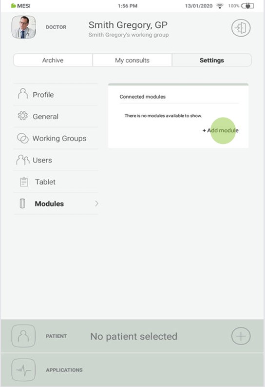
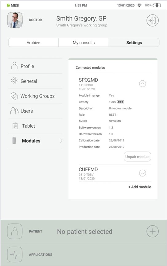
Go to User profile > Settings > Modules > +Add module
Step 2
Press the button on the top of the MESI PULSE OXIMETER UNIT.
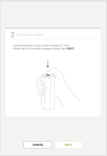
Step 3
When the MESI mTABLET UNIT establishes a connection with MESI PULSE OXIMETER UNIT, the light on top of the module will change. Confirm the pairing process by pressing the button on top of the module again.
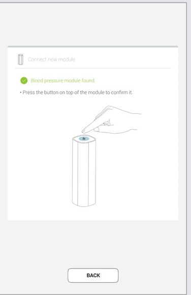
Step 4
Final screen indicates successful connection between the MESI mTABLET UNIT and the MESI PULSE OXIMETER UNIT. It is possible to access additional information about the connected modules in User profile >Settings > Modules > Connected modules
NOTE: While operating only with one MESI mTABLET UNIT, then performing this operation is required only once. In case of more MESI mTABLET UNITS this process will have to be repeated on each MESI mTABLET UNIT.
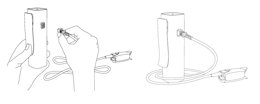
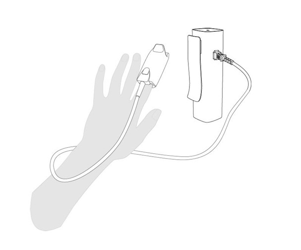
5.1.6 CONNECTING PATIENT CABLE
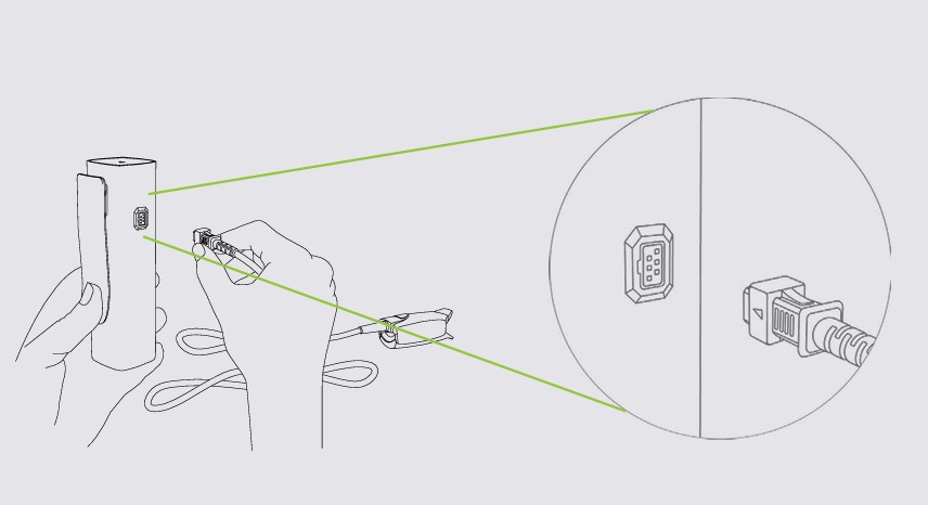
Before first use, during transportation and when storing for longer periods, the sensor should be disconnected from the MESI PULSE OXIMETER UNIT. To connect the FingerClip Sensor (CS10299), follow the next steps:
Step 1
Hold resting MESI PULSE OXIMETER UNIT and the FingerClip Sensor cable (CS10299) in your hands firmly.
Step 2
Connect the FingerClip Sensor (CS10299) to the MESI PULSE OXIMETER UNIT as shown below.
5.2 PATIENT SELECTION
Before performing a measurement, patient needs to be selected or added to your working groups patient list.
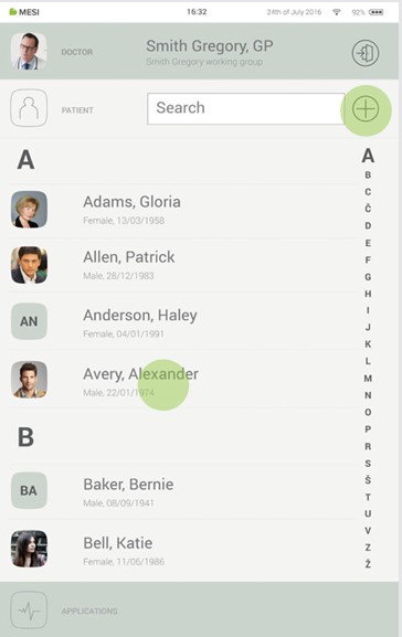
5.2.1 SELECTING A PATIENT
Step 1
Select the patient tab button.
Step 2
Use the search bar (1) or scroll (2) to the patient who is having their blood pressure measured.
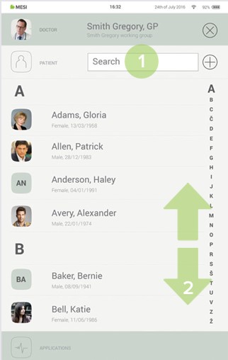
Step 3
Select the patient.

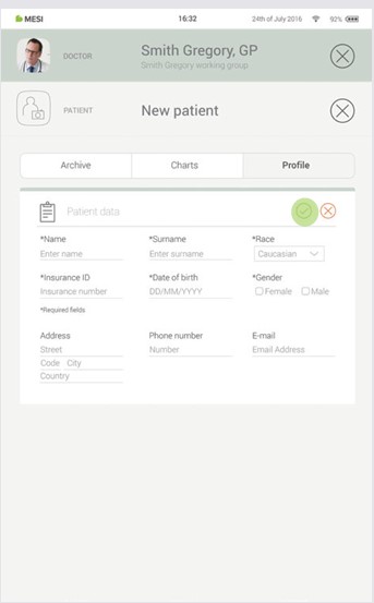
5.2.2 ADDING A PATIENT
Step 1
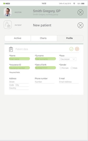
On your home screen, press the + button in the Patient tab.
Step 2
Fill out required fields (Name, Surname, Date of Birth and Gender) and any additional information regarding the patient.
Step 3
Save the patient by pressing the ✔️ button.
Standard accessories include FingerClip Sensor (CS10299).
Before first measurement it is advised for the patient to wash hands. This will reduce transmission of microorganisms and body secretions.
Remove anything on the site of application that absorbs light (such as dried blood or nail polish).
Warm the area where the FingerClip Sensor (CS10299) will be attached.
Clear out any sources of environmental interference (high levels of light).
Attach the FingerClip Sensor (CS10299) to the finger (usually middle or index finger) and try to minimize movement.
NOTE: For other sensors observe Instructions for use of the sensor available in the MESI package or contact your local distributor for more information.
5.3.1 STEP-BYSTEP SpO₂ MEASUREMENT
Step 1
On the MESI mTABLET UNIT select existing patient or add a new one. For additional information see chapter 5.2 PATIENT SELECTION.
Step 2
After selecting the patient, select the SpO₂ application in application menu.
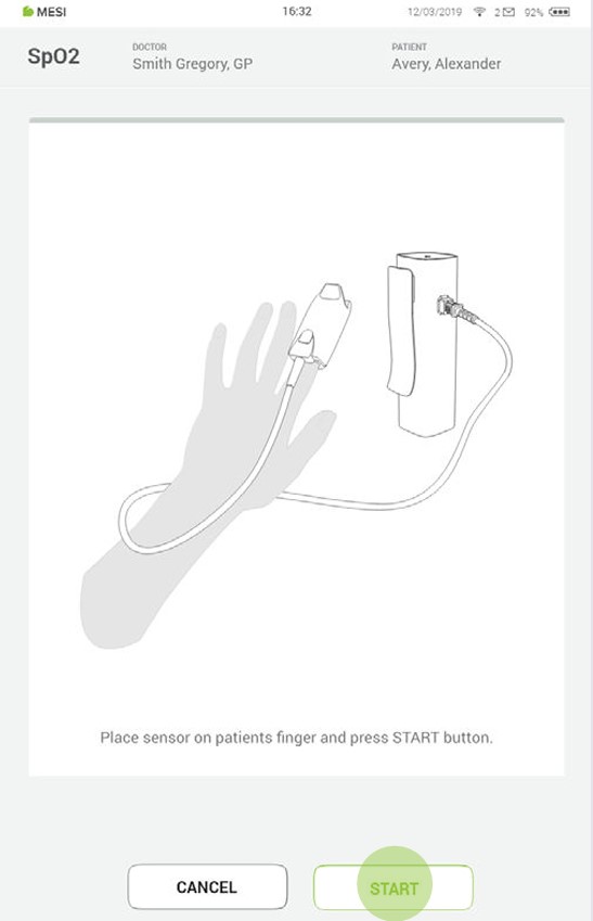
Step 3
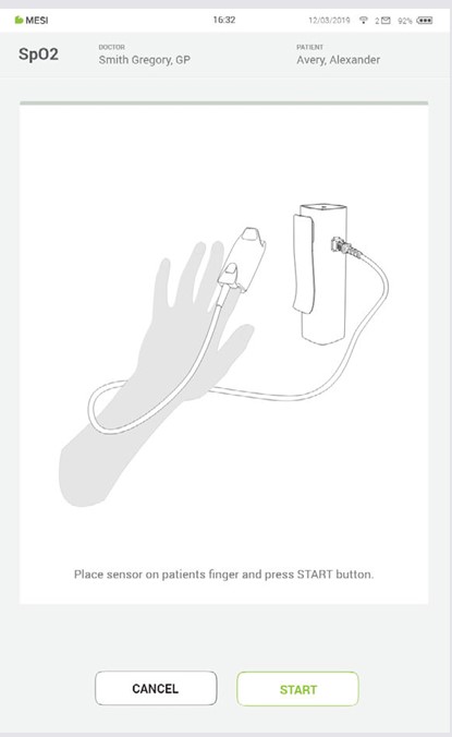
Apply the SpO₂ sensor on appropriate location and press START button.
NOTE: If MESI PULSE OXIMETER UNIT has low battery or connectivity issues notifications will be displayed on instructions screen. In case of errors advise the chapters 8 ERRORS and 9 TROUBLESHOOTING.
Step 4
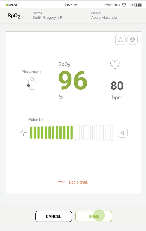
The measuring screen displays oxygen saturation level (%) and pulse rate (SpO₂).
Step 5
After about 30 s or when the SpO₂ values stabilize press DONE button on the bottom of the screen to record the current SpO₂ and heart rate values.
NOTE: The measurement of oxygen saturation can be affected by the following factors: ambient light, nail polish, skin pigment, damaged sensor, improper placement of sensor and muscle tremor.
NOTE: Poor peripheral perfusion or cold fingers can cause low perfusion, or blood f low, which can lead the oximeter to make an inaccurate reading. The application site can be warmed before measurement or the sensor should be repositioned.
5.3.2 ADITIONAL SETTINGS
During the SpO₂ measurement there are Additional settings and alerts, which can be changed:
The area of minimum and maximum saturation alert. After change this can be saved as a default values.
Alert volume – set the volume alert by sliding or tapping left/ right on the slide bar.
Pulse bar volume – set the pulse bar volume by sliding or tapping left/right on the slide bar.
Device volume – set the device volume by sliding or tapping left/right on the slide bar.
5.4 REVIEWING SpO₂ MEASUREMENT
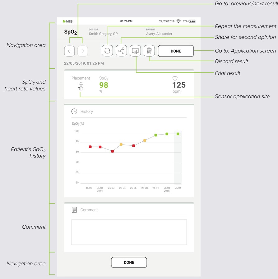
5.4.1 MESI MTABLET RESULTS SCREEN
When the measurement process is completed, result will be displayed on the screen. It consists of five different areas: navigation area, numeric result of SpO₂ and HR, patient’s measurements history, comments on the result, and another navigation area.
5.4.1.1 Navigation area
The buttons in the navigation area can toggle between previous and next measurement of the patient. If the user is not satisfied with the measurement for any reason, it can be discarded or repeated. In case of uncertainty, the user can consult with other doctors by simply sending the measurement through the email.
The SpO₂ and pulse rate measurement can be viewed immediately on the MESI mTABLET UNIT for further analysis. With standard software the MESI PULSE OXIMETER UNIT is used for spot-checking of patients during no-motion conditions.
5.4.1.3 Patient measurement history
History holds an overview of measurements done by the same doctor on the same patient. It shows the trend of the patient’s results.
A comment can be added to every measurement. It will be stored and always available together with recoding report.
Even though most of the MESI PULSE OXIMETER UNIT control is done through the MESI mTABLET UNIT interface there is still a multifunctional LED button on top of the device. Next to basic colour light notification functionalities of this button there is also a possibility to perform some additional operations. These operations are based on the current status of the MESI PULSE OXIMETER UNIT.
5.5.1 LED INDICATORS
5.5.1.1 Standby
Green: Battery capacity is more than 25%.
Red: Unit battery is less than 25%, please recharge the unit as soon as possible.
5.5.1.2 Charging
Green: Battery is fully charged.
Orange: Unit is charging.
5.5.1.3 Pairing
Blue: Unit is waiting for confirmation from the mTABLET.
5.5.2.1 Standby
Button functions - Standby| Column A | Column B |
|---|
| Status check | Quick press on button in standby mode will perform a basic status check of MESI PULSE OXIMETER UNIT – green, more than 25 % battery charge, while red means less than 25 % charge is left, and the module should be charged. |
| Pairing mode | Holding the button for 4 seconds will put the module into pairing mode where it can be connected to MESI mTABLET UNIT (for more information look at chapter 5.1.5 PAIRING). |
| Resetting the diagnostic module | To perform a reset of the MESI PULSE OXIMETER UNIT press and hold the LED button for 10 seconds until it changes colour to red. Unit will be ready to use in a few seconds. |
5.5.2.2 Measurement mode
Button functions - Measurement mode| Column A | Column B |
|---|
| Stop measuring | Pressing the top button on the MESI PULSE OXIMETER UNIT quickly while performing the SpO₂ measurement will stop the measurement. |
Maintenance
6.1 CHARGING THE BATTERY
The device can be only used on battery power therefore it has to be ensured that the battery is charged regularly. One battery charge is sufficient for approximately 8000 measurements or 56 hours of continuous use.
To charge the battery, place the MESI PULSE OXIMETER UNIT on the MESI LARGE CHARGING PLATE UNIT. During the charging process the light on the module will be flashing orange. Only when the device is completely charged it will start flashing green. For more information see chapter 5.5 MULTIFUNCTIONAL LED BUTTON.
If the capacity of the battery is significantly decreased after a certain period of intensive use, the battery is most likely spent, and it should be replaced. As the device does not contain any parts which can be replaced by a user, contact your local distributor or the manufacturer about replacing the battery.
6.2 CLEANING INSTRUCTIONS
⚠️Read and follow cleaning instructions carefully.
Reusable pulse oximetry sensors
The pulse oximeter sensor must be carefully cleaned and disinfected after every use and before use with a different patient. The sensor can be reused on the same patient, for the patient’s entire stay. If the sensor is covered with dust and dirt, it can affect the performance of the device. Observe the cleaning instructions in the Instructions for Use that came with the sensor.
⚠️Do not use aggressive cleaning agents, volatile liquids or excessive force when cleaning the device. Don’t dip the sensor in liquids or cleaning agents.
MESI PULSE OXIMETER UNIT
Before cleaning remove the MESI PULSE OXIMETER UNIT from the charging station and disconnect the sensor from the MESI PULSE OXIMETER UNIT.
Use a soft lint-free cloth dampened with a proper cleaning agent to clean and disinfect the exterior and interior of the unit/sensor.
With a dry cloth wipe off all residues of the cleaning solution.
Dry the equipment before next use.
Recommended cleaning agents:
Not approved cleaning agents:
6.3 PRODUCT LIFE AND STORAGE
If correctly used and maintained the device will have a minimum service life of 5 years. It is possible to store the device in suitable conditions for a maximum of 5 years. While in storage the battery needs to be recharged once per month to avoid accidentally over-discharging the batteries. When using the device after storage, we recommend subjecting the device to a thorough maintenance check. The device should be inspected by a qualified service engineer at least every 12 months for the following safety checks:
any mechanical or functional damage on device and accessories,
performance of device in accordance to instructions for use,
legibility of labels,
battery cycle count.
General warnings
7.1 MEASUREMENT PROCEDURE
⚠️This product is not designed for sterile use.
⚠️Do not use this unit in areas where there in the presence of flammable gases such as anaesthetic agents or in an oxygen-rich environment.
⚠️Do not place the sensor on wounds, as this may cause additional injury.
7.2 MAINTENANCE
⚠️Before cleaning disconnect from the mains. Due to constant standby mode of the device do not clean terminals.
⚠️Do not, under any circumstances, immerse the unit or cable assemblies in liquid.
⚠️Do not use high-temperature sterilization processes (such as autoclaving). Do not use e-beam or gamma radiation sterilization.
⚠️Do not dispose of the device as unsorted municipal waste. Prepare it for recycling or separate waste collection in accordance with Directive 2002/96/EC on scrap electrical and electronic equipment (WEEE).
⚠️The AC/DC power supply must be connected to an easily accessible socket (the AC/DC power supply also serves for galvanic isolation).
7.3 FUNCTIONING OF THE DEVICE
⚠️Regularly inspect sensor and cable for any signs of damage. Do not use damaged sensor as the accuracy cannot be assured.
⚠️To prevent electric shock hazard due to current leakage, only use AC/DC power supplies which are compliant with the technical specifications of the device.
⚠️To prevent electric shock or damage to the device do not disassemble the unit. The device does not contain any parts which can be replaced or serviced by a user. If a defect occurs, consult your dealer or distributor.
⚠️Important information on electromagnetic compatibility (EMC). As the number of electronic devices such as computers and mobile phones in the room increases, medical devices can become sensitive to the electromagnetic influences of other devices. Electromagnetic interference can cause medical devices to malfunction, which can potentially lead to dangerous situations. Furthermore, medical devices must not interfere with other devices. The IEC/EN 60601-1-2 standard was introduced due to the necessity to establish electromagnetic compatibility (EMC) requirements for the prevention of dangerous situations in the use of medical devices. The standard defines the level of resistance to electromagnetic interference for medical devices. This medical device is compliant with the IEC/EN 60601-1-2 standard in terms of resistance to electromagnetic interference and electromagnetic emissions. Nevertheless, do not use mobile phones and similar devices which create strong electromagnetic fields in the vicinity of the device. This can cause the device to malfunction, which can potentially cause a dangerous situation.
⚠️Portable RF communications equipment including peripherals such as antenna cables and external antennas should be used no closer than 30 cm (12 inches) to any part of the MESI mTABLET SPO2 including cables specified by the manufacturer. Otherwise the degradation of the performance of this equipment could result.
⚠️Use of this equipment adjacent to or stacked with other equipment should be avoided because it could result in improper operation. If such use is necessary, this equipment should be observed to verify that they are operating normally.
⚠️Use of accessories, transducers and cables other than those specified or provided by the manufacturer of this equipment could result in increased electromagnetic emissions or decreased electromagnetic immunity of this equipment and result in improper operation.
Errors
Errors| Error | Description | Solution |
|---|
| N21: SPO2MD module not in range. | MESI PULSE OXIMETER UNIT is out of range. | Bring the MESI PULSE OXIMETER UNIT closer to the tablet and restart the SpO₂ application. |
| N22: SPO2MD module not paired with MESI mTABLET UNIT. | MESI PULSE OXIMETER UNIT is not paired to the tablet. | Pair the MESI PULSE OXIMETER UNIT to the MESI mTABLET UNIT. For pairing see chapter 5.1.5 PAIRING. |
| N23: SPO2MD module battery cycle count is high. | Battery needs to be replaced. | Please contact MESI representative to replace the battery. |
| E24: Depleted battery. Measurement ended. | MESI SPO2 MODULE battery is empty. | Place the MESI SPO2 MODULE to the MESI LARGE CHARGING PLATE UNIT. |
| N61: Connection to diagnostic module has been interrupted. Please restart the recording process. | An error occurred to the SPO2MD module, or there might be a communication problem between the module and the MESI mTABLET (MTABMD). | Restart the SpO2 application and the recording process. |
| N62: Sensor not detected. | Sensor not detected. | Reconnect the sensor. |
| N63: Weak pulse signal. | Problem with application site. | Check the sensor size and the sensor application site and remove anything that absorbs light (dried blood, nail polish). |
| N63: Weak pulse signal. | Too much movement. | The most common cause of inaccurate oximeter readings is excessive movement. Try to reduce the patient movement. |
| N64: Finger not detected. | The sensor is not on the finger. | Put the sensor on the finger. |
| N65: Operating temperature too high. | Device is too hot. | Leave the device to cool down for few minutes and then start the measuring process again. |
| N66: Too much ambient light. | There is too much light on the SpO₂ sensor. | High levels of ambient light, such as overhead lights, phototherapy lights and infrared warmers, can blind the light sensor and give an inaccurate reading. Troubleshoot by reapplying the sensor or shielding the sensor with a towel or blanket to minimize the ambient light. |
| N67: Connect the sensor to the module. | The sensor is disconnected. | Check, if the connector is disconnected out of the MESI PULSE OXIMETER UNIT and connect it to the MESI PULSE OXIMETER UNIT. |
Troubleshooting
Troubleshooting| Column A | New Column | Column B |
|---|
| Continuously flashing purple or red indicator on MESI PULSE OXIMETER UNIT. | Incorrect state of the diagnostic module. | Press and hold the button on top of the MESI PULSE OXIMETER UNIT for 15 seconds to restart it. The light should start flashing. |
| No light shows when the multifunctional button on top of the MESI PULSE OXIMETER UNIT is pressed. | Depleted battery. | Place the MESI PULSE OXIMETER UNIT on the charging station and leave it to charge for at least half an hour before retrying. |
| SpO2measurement will not start even though the MESI PULSE OXIMETER UNIT is paired and next to MESI mTABLET UNIT. | Possibility of electromagnetic interference. | Make sure that there aren’t any devices nearby which produce electromagnetic interference. These devices can interfere with the basic functions of the MESI mTABLET UNIT, which can potentially lead to dangerous situations. |
NOTE: If the problem continues, contact the manufacturer or the local distributor for further assistance.
Warranty information
For the SPO2SYS systems purchased from April 1, 2026 on, the company MESI Ltd. hereby ensures a warranty period up to two years, which begins with the date of purchase (delivery date shown on the invoice). The warranty is valid with an invoice or a copy of the invoice. The Company MESI Ltd. also guarantees that the SPO2SYS system you have purchased is free from defects in materials and is made from suitable materials. In the warranty period the company MESI Ltd. guarantees a free repair of defective device or parts covered by this warranty. If the defective device in the warranty period cannot be repaired, a free replacement will be provided. The company MESI Ltd. will ensure maintenance and supply spare parts for a period of ten years from the date of purchase as long as (spare) parts are available from suppliers.
The warranty does not cover:
The cost of repairs and/or damage done by an unauthorized person. If you wish to make a warranty claim, please contact your local distributor or the manufacturer of the SPO2SYS system, whose contact details can be found at the company’s website.
Regular inspections (at the customer’s request) and/or maintenance (replacement of worn parts).
Deterioration of accessories and other additions other than the main device.
Costs incurred due to disagreement with the warranty conditions (it shall be charged).
Any damage caused by accidents, misuse, neglect, abrasion, exposure to extreme temperatures, solvents, acids, water, normal wear and tear or damage in transit, theft or loss.
Use of the device for purposes other than its intended use.
Damage caused by airline or freight company mishandling.
Improper use or abuse of SPO2SYS system, including but not solely limited to the failure to use this product for its normal purposes or in accordance with company’s instructions on usage and maintenance.
Defects resulting from usage of the product in conjunction with accessories that are not approved by company MESI Ltd. for use with the SPO2SYS system.
Defects or deficiencies of the SPO2SYS system arising from incorrect installation or use not consistent with the instructions and technical or safety standards prescribed in the device’s user manual.
Accidents, Acts of God, lightning, water, fire, public disturbances, improper ventilation, voltage fluctuations or any cause beyond the control of company MESI Ltd.
Damage to the battery caused by failing to charge the empty battery regularly, or failure to use in accordance with the instructions of user manual.
Replacement or repair of defective device or its parts, if the serial number on the product has been altered, deleted, removed or made illegible.
| Column A | Column B |
|---|
| Parts included in the two-year warranty | Pulse oximetry measurement unit |
| Parts included in the one-year warranty | SpO2 sensors (EarClip, Wrap, FingerClip, SoftTip) |
| Parts excluded from warranty | Packaging |
All of the above is the sole and exclusive warranty for the SPO2SYS system.
We state:
That during the warranty period the SPO2SYS system will work flawlessly, if handled as stated in the instructions for use and if maintained regularly.
That the warranty period commences on the date of purchase.
That in the warranty period the defects and technical deficiencies of the SPO2SYS system that are generated during normal use will be eliminated at company’s own expense.
That the SPO2SYS system will be fully operational, if optimum conditions for the operation of the product, ranging from 10-40 °C, max. 80% humidity, non-condensing and without excessive amounts of dust and dirt, are fulfilled.
That the warranty is not applicable to cases other than defects in material and workmanship.
That the warranty is void if the SPO2SYS system is used in a rental capacity and damaged at the same time.
That the repair or replacement under the terms of this warranty does not provide the right to extension or renewal of the warranty period.
That the warranty will be void if payments are not received by company MESI Ltd. in the period after any agreed upon credit terms expire.
Description of the warranty claim process:
The warranty is valid only if the SPO2SYS system and its parts are returned during the applicable warranty period, together with the original invoice or its copy issued by the manufacturer of the device. If necessary, give a description of the problem. In case the invoice is not presented, the company MESI Ltd. holds the right to void the warranty.
Standard compliance
The provisions of the Council Directive 93/42/EEC concerning medical devices were complied with. The standards in the table below were complied with.
Standard compliance| Reference number | Description |
|---|
| EN 60601-1:2006/ A1:2013 | Medical electrical equipment - Part 1: General requirements for basic safety and essential performance |
| EN 60601-1-6:2010/ A1:2015 | Medical electrical equipment – Part 1-6: General requirements for basic safety and essential performance - Collateral standard: Usability |
| EN ISO 80601-261:2011 | Medical electrical equipment – Part 2-61: Particular requirements for basic safety and essential performance of pulse oximeter equipment |
| EN 62304:2006/ A1:2015 | Medical device software - Software lifecycle processes |
| EN 62366:2015 | Medical devices - Application of usability engineering to medical devices |
| EN 60601-1-2:2015 | Medical electrical equipment - Part 1-2: General requirements for basic safety and essential performance - Collateral Standard: Electromagnetic disturbances - Requirements and tests |
| EN ISO 152231:2016 | Symbols for use in the labelling of medical devices |
| EN 303 446-1:2017 | Electromagnetic Compatibility (EMC) standard for combined and/or integrated radio and non-radio equipment; Part 1: Specific conditions for equipment in residential locations. |
| EN ISO 14971:2012 | Medical devices – Application of risk management to medical devices |
| EN ISO 80601-2- 61:2019 | Medical electrical equipment – Part 2-61: Particular requirements for basic safety and essential performance of pulse oximeter equipment |
| EN ISO 109931:2009 /AC:2010 | Biological evaluation of medical devices – Part 1: Evaluation and testing within a risk management process |
| EN ISO 13485:2016 | Medical devices – Quality management systems – Requirements for regulatory purposes |
11.1. MANUFACTURER DECLARATION ON EMC
MESI mTABLET SPO2 is intended for use in the electromagnetic environment specified below. The customer or the user of the above listed models should assure that they are used in such an environment.
Manufacturer declaration on EMC| Emissions test | Compliance | Electromagnetic environment - guidance |
|---|
| RF emissions CISPR 11 | Group 1 | The above listed models use RF energy only for its internal function. Therefore, its RF emissions are very low and are not likely to cause any interference in nearby electronic equipment. |
| RF emissions CISPR 11 | Class B | MESI mTABLET SPO2 is suitable for use in all establishments, including domestic establishments and those directly connected to the public low-voltage power supply network that supplies buildings used for domestic purposes. |
| Harmonic emissions IEC 61000-3-2 | N/A | MESI mTABLET SPO2 is suitable for use in all establishments, including domestic establishments and those directly connected to the public low-voltage power supply network that supplies buildings used for domestic purposes. |
| Voltage fluctuations / flicker emissions IEC 61000-3-3 | Complies | MESI mTABLET SPO2 is suitable for use in all establishments, including domestic establishments and those directly connected to the public low-voltage power supply network that supplies buildings used for domestic purposes. |
MESI mTABLET SPO2 is intended for use in the electromagnetic environment specified below. The customer or the user of the above listed models should assure that they are used in such an environment.
Patient coupling PORT
Patient coupling PORT| Immunity Test | Test Condition | IEC 60601 Compliance level | Electromagnetic environment - guidance |
|---|
| Electrostatic discharge (ESD) according to IEC 61000-4-2 | ± 8 kV Contact
± 2, 4, 8, 15 kV Air | ± 8 kV Contact
± 15 kV Air | Floors should be wood, concrete or ceramic tile. If floors are covered with synthetic material, the relative humidity should be at least 30%. |
| Conducted RF induced by RF fields IEC 61000-4-6 (a) | 3 Vrms 150 kHz - 80 MHz
6 Vrms in ISM bands between 150 kHz - 80 MHz c)
80% AM 1kHz | Exempt from this requirement - cable length is less than 3 m | - |
Comment: *Not applicable, unit, without Signal input/output parts PORT
a) SIP/SOPS whose maximum cable length is less than 3 m in length are excluded.
b) This test applies only to output lines intended to connect directly to outdoor cables.
c) The ISM (industrial, scientific and medical) bands between 0,15 MHz and 80 MHz are 6,765 MHz to 6,795 MHz; 13,553 MHz to 13,567 MHz; 26,957 MHz to 27,283 MHz; and 40,66 MHz to 40,70 MHz. The amateur radio bands between 0,15 MHz and 80 MHz are 1,8 MHz to 2,0 MHz, 3,5 MHz to 4,0 MHz, 5,3 MHz to 5,4 MHz, 7 MHz to 7,3 MHz, 10,1 MHz to 10,15 MHz, 14 MHz to 14,2 MHz, 18,07 MHz to 18,17 MHz, 21,0 MHz to 21,4 MHz, 24,89 MHz to 24,99 MHz, 28,0 MHz to 29,7 MHz and 50,0 MHz to 54,0 MHz.
MESI mTABLET SPO2 is intended for use in the electromagnetic environment specified below. The customer or the user of the above listed models should assure that they are used in such an environment.
Enclosure Port
Enclosure Port| Immunity Test | Test Condition | IEC 60601 Compliance level | Electromagnetic environment - guidance |
|---|
| Electrostatic discharge (ESD) IEC 61000-4-2 | ±,8 kV Contact
± 2, 4, 8, 15 kV Air | ±8 kV Contact
± 15 kV Air* | Floors should be wood, concrete or ceramic tile. If floors are covered with synthetic material, the relative humidity should be at least 30% |
| Radiated RF EM fields and Proximity fields from RF wireless communications equipment
IEC 61000-4-3 | 3 V/m
80 MHz – 2.7 GHz
80% AM 1 kHz | 3 V/m
80 MHz – 2.7 GHz | Mains power quality should be that of a professional healthcare facility environment and Home healthcare environment. |
| Radiated RF EM fields and Proximity fields from RF wireless communications equipment
IEC 61000-4-3 | 385 MHz (18Hz Pulse Modulation) | 27 V/m | Mains power quality should be that of a professional healthcare facility environment and Home healthcare environment. |
| Radiated RF EM fields and Proximity fields from RF wireless communications equipment
IEC 61000-4-3 | 450 MHz (FM+/-5 KHz deviation 1 kHz sine or 18 Hz Pulse Modulation) | 28 V/m | Mains power quality should be that of a professional healthcare facility environment and Home healthcare environment. |
| Radiated RF EM fields and Proximity fields from RF wireless communications equipment
IEC 61000-4-3 | 710 MHz (217 Hz PM) | 9 V/m | Mains power quality should be that of a professional healthcare facility environment and Home healthcare environment. |
| Radiated RF EM fields and Proximity fields from RF wireless communications equipment
IEC 61000-4-3 | 745 MHz (217 Hz PM) | 9 V/m | Mains power quality should be that of a professional healthcare facility environment and Home healthcare environment. |
| Radiated RF EM fields and Proximity fields from RF wireless communications equipment
IEC 61000-4-3 | 780 MHz (217 Hz PM) | 9 V/m | Mains power quality should be that of a professional healthcare facility environment and Home healthcare environment. |
| Radiated RF EM fields and Proximity fields from RF wireless communications equipment
IEC 61000-4-3 | 810 MHz (18 Hz PM) | 28 V/m | Mains power quality should be that of a professional healthcare facility environment and Home healthcare environment. |
| Radiated RF EM fields and Proximity fields from RF wireless communications equipment
IEC 61000-4-3 | 870 MHz (18 Hz PM) | 28 V/m | Mains power quality should be that of a professional healthcare facility environment and Home healthcare environment. |
| Radiated RF EM fields and Proximity fields from RF wireless communications equipment
IEC 61000-4-3 | 930 MHz (18 Hz PM) | 28 V/m | Mains power quality should be that of a professional healthcare facility environment and Home healthcare environment. |
| Radiated RF EM fields and Proximity fields from RF wireless communications equipment
IEC 61000-4-3 | 1720 MHz (217 Hz PM) | 28 V/m | Mains power quality should be that of a professional healthcare facility environment and Home healthcare environment. |
| Radiated RF EM fields and Proximity fields from RF wireless communications equipment
IEC 61000-4-3 | 1845 MHz (217 Hz PM) | 28 V/m | Mains power quality should be that of a professional healthcare facility environment and Home healthcare environment. |
| Radiated RF EM fields and Proximity fields from RF wireless communications equipment
IEC 61000-4-3 | 1970 MHz (217 Hz PM) | 28 V/m | Mains power quality should be that of a professional healthcare facility environment and Home healthcare environment. |
| Radiated RF EM fields and Proximity fields from RF wireless communications equipment
IEC 61000-4-3 | 2450 MHz (217 Hz PM) | 28 V/m | Mains power quality should be that of a professional healthcare facility environment and Home healthcare environment.
|
| Radiated RF EM fields and Proximity fields from RF wireless communications equipment
IEC 61000-4-3 | 5240 MHz (217 Hz PM) | 9 V/m | Mains power quality should be that of a professional healthcare facility environment and Home healthcare environment.
|
| Radiated RF EM fields and Proximity fields from RF wireless communications equipment
IEC 61000-4-3 | 5500 MHz (217 Hz PM) | 9 V/m | Mains power quality should be that of a professional healthcare facility environment and Home healthcare environment.
|
| Radiated RF EM fields and Proximity fields from RF wireless communications equipment
IEC 61000-4-3 | 5785 MHz (217 Hz PM) | 9 V/m | Mains power quality should be that of a professional healthcare facility environment and Home healthcare environment.
|
| RATED power frequency magnetic fields
IEC 61000-4-8 | 50 Hz or 60 Hz | 30 A/m |
Power frequency magnetic fields should be at levels characteristic of a typical location in a typical commercial or hospital environment. |
MESI mTABLET SPO2 is intended for use in the electromagnetic environment specified below. The customer or the user of the above listed models should assure that they are used in such an environment.
Input a.c. power PORT
Input a.c. power PORT| Immunity Test | Test Condition | IEC 60601 Compliance level | Electromagnetic environment - guidance |
|---|
| Electrical fast transient/bursts IEC 610004-4 | ± 2 kV
100 kHz Repetition frequency | ± 2 kV | Mains power quality should be that of a professional healthcare facility environment and Home healthcare environment. |
| Surges
IEC 61000-4-5 | ± 0.5 kV, ±1 kV line(s) to line(s)
± 0.5 kV, ±1 kV , ± 2 kV line(s) to ground (a) | ± 1 kV
Differential mode | Mains power quality should be that of a professional healthcare facility environment and Home healthcare environment. |
| Conducted RF induced by RF fields IEC 61000-4-6 | 3 Vrms 150 kHz - 80 MHz
6 Vrms in ISM bands between 150 kHz - 80 MHz c)
80% AM 1kHz | 3 Vrms 150 kHz - 80 MHz
6 Vrms in ISM bands between 150 kHz - 80 MHz c)
80% AM 1 kHz | Mains power quality should be that of a professional healthcare facility environment and Home healthcare environment. |
| Voltage dips, short interruptions and voltage variations on power supply input lines IEC 61000-4-11 | 0% UT;
0°.45°, 90°, 135°, 180°, 225°, 270°, 315°
0% UT;
0°
0% UT;
70%
0% UT;
0% | 0.5 Cycles
1 Cycle
25/30 cycles (50/60 Hz)
250/300 Cycles (50/60 Hz) (5 s) | Mains power quality should be that of a professional healthcare facility environment and Home healthcare environment.
If the user of the above listed models requires continued operation during power mains interruptions, it is recommended that MESI mTABLET BP is powered from an uninterruptible power supply or battery. |
Comment:
a) Not applicable to CLASS II ME EQUIPMENT and ME SYSTEMS.
b) The ISM (industrial, scientific and medical) bands between 0.15 MHz and 80 MHz are 6.765 MHz to 6.795 MHz; 13.553 MHz to 13.567 MHz; 26.957 MHz to 27.283 MHz; and 40.66 MHz to 40.70 MHz. The amateur radio bands between 0.15 MHz and 80 MHz are 1.8 MHz to 2.0 MHz, 3.5 MHz to 4.0 MHz, 5.3 MHz to 5.4 MHz, 7 MHz to 7.3 MHz, 10.1 MHz to 10.15 MHz, 14 MHz to 14.2 MHz, 18.07 MHz to 18.17 MHz, 21.0 MHz to 21.4 MHz, 24.89 MHz to 24.99 MHz, 28.0 MHz to 29.7 MHz and 50.0 MHz to 54.0 MHz.
MESI mTABLET SPO2 is intended for use in the electromagnetic environment specified below. The customer or the user of the above listed models should assure that they are used in such an environment.
Signal input/output parts PORT
Signal input/output parts PORT| Immunity Test | Test Condition | IEC 60601 Compliance level | Electromagnetic environment - guidance |
|---|
| Electrostatic discharge (ESD) IEC 61000-4-2 | ±,8 kV Contact
± 2, 4, 8, 15 kV Air | ±8 kV Contact
± 15 kV Air | Floors should be wood, concrete or ceramic tile. If floors are covered with synthetic material, the relative humidity should be at least 30%. |
| Electrical fast transient/bursts IEC 610004-4 (a) | ± 1 kV
100 kHz Repetition frequency | ± 1 kV | Mains power quality should be that of a professional healthcare facility environment and Home healthcare environment. |
| Surges IEC 61000-4-5 (b) | ±2 kV line(s) to ground | Not applicable. | Mains power quality should be that of a professional healthcare facility environment and Home healthcare environment. |
| Conducted RF induced by RF fields IEC 61000-4-6 (a) | 3 Vrms
150 kHz - 80 MHz
6 Vrms in ISM bands between 150 kHz - 80 MHz c) 80% AM 1kHz | 3 Vrms
150 kHz - 80 MHz
6 Vrms in ISM bands between 150 kHz - 80 MHz c) 80% AM 1 kHz | Mains power quality should be that of a professional healthcare facility environment and Home healthcare environment. |
Comment:
a) Not applicable to CLASS II ME EQUIPMENT and ME SYSTEMS.
b) The ISM (industrial, scientific and medical) bands between 0.15 MHz and 80 MHz are 6.765 MHz to 6.795 MHz; 13.553 MHz to 13.567 MHz; 26.957 MHz to 27.283 MHz; and 40.66 MHz to 40.70 MHz. The amateur radio bands between 0.15 MHz and 80 MHz are 1.8 MHz to 2.0 MHz, 3.5 MHz to 4.0 MHz, 5.3 MHz to 5.4 MHz, 7 MHz to 7.3 MHz, 10.1 MHz to 10.15 MHz, 14 MHz to 14.2 MHz, 18.07 MHz to 18.17 MHz, 21.0 MHz to 21.4 MHz, 24.89 MHz to 24.99 MHz, 28.0 MHz to 29.7 MHz and 50.0 MHz to 54.0 MHz.
Guidance and manufacturer’s declaration - electromagnetic immunity
MESI mTABLET SPO2 is intended for use in the electromagnetic environment specified below. The customer or the user of the above listed models should assure that they are used in such an environment.
Guidance and manufacturer’s declaration - electromagnetic immunity| Immunity test | IEC 60601 Test level | Compliance level | Electromagnetic environment - guidance |
|---|
| Conducted RF induced by RF fields IEC 61000-4-6
Radiated RF EM fields and Proximity fields from RF wireless communications equipment IEC 61000-4-3 | 3 Vrms 150 kHz - 80 MHz 6 Vrms in ISM bands between 150 kHz - 80 MHz c)
3 V/m 80 MHz – 2.7 GHz | 3 Vrms 150 kHz - 80 MHz 6 Vrms in ISM bands between 150 kHz - 80 MHz c)
3 V/m | Portable and mobile RF communications equipment should not be used no closer to any part of the above listed models, including cables, than the recommended separation distance calculated from the equation applicable to the frequency of the transmitter.
Recommended separation distance
d = 1.2√P
d = 1.2√P 80 MHz - 800 MHz
d = 2.3√P 800 MHz – 2.7 GHz
Where P is the maximum output power rating of the transmitter in watts (W) according to the transmitter manufacturer and d is the recommended separation distance in meters (m). Field strengths from fixed RF transmitters, as determined by an electromagnetic site survey a should be less than the compliance level in each frequency range. (b) Interference may occur in the vicinity of equipment marked with the following symbol: |
NOTE 1: At 80 MHz and 800 MHz, the higher frequency range applies.
NOTE 2: These guidelines may not apply in all situations. Electromagnetic propagation is affected by absorption and reflection from structures, objects and people.
a) Field strengths from fixed transmitters such as base stations for radio (cellular/cordless) telephones, land mobile radios, amateur radio, AM and FM radio broadcast and TV broadcast, cannot be predicted theoretically with accuracy. To assess the electromagnetic environment due to fixed RF transmitters an electromagnetic site survey should be considered. If the measured field strength in the location in which MESI mTABLET ABI is used, exceeds the applicable RF compliance level above, the above listed models should be observed to verify normal operation. If abnormal performance is observed, additional measures may be necessary, such as reorienting or relocating the above listed models.
b) Over the frequency range 150 kHz to 80 MHz, field strength should be less than 3 V/m.
c) The ISM (industrial, scientific and medical) bands between 0.15 MHz and 80 MHz are 6.765 MHz to 6.795 MHz; 13.553 MHz to 13.567 MHz; 26.957 MHz to 27.283 MHz; and 40.66 MHz to 40.70 MHz. The amateur radio bands between 0.15 MHz and 80 MHz are 1.8 MHz to 2.0 MHz, 3.5 MHz to 4.0 MHz, 5.3 MHz to 5.4 MHz, 7 MHz to 7.3 MHz, 10.1 MHz to 10.15 MHz, 14 MHz to 14.2 MHz, 18.07 MHz to 18.17 MHz, 21.0 MHz to 21.4 MHz, 24.89 MHz to 24.99 MHz, 28.0 MHz to 29.7 MHz and 50.0 MHz to 54.0 MHz.
Recommended separation distances between portable and mobile RF communications equipment and the above listed models
MESI mTABLET SPO2 is intended for use in the electromagnetic environment in which radiated RF disturbances are controlled. The customer or the user of the above listed models can help prevent electromagnetic interference by maintaining a minimum distance between portable and mobile RF communications equipment (transmitters) and the above listed models as recommended below, according to the maximum output power of the communication equipment.
Separation distance according to frequency of transmitter m
Separation distance according to frequency of transmitter m| Rated maximum output power of transmitter W | 150 kHz to 80 MHz d = 1.2√P | 80 MHz to 800 MHz d = 1.2√P | 800 MHz to 2.5 GHz d = 2.3 √P |
|---|
| 0.01 | 0.12 | 0.12 | 0.23 |
| 0.1 | 0.38 | 0.38 | 0.73 |
| 1 | 1.2 | 1.2 | 2.3 |
| 10 | 3.8 | 3.8 | 7.3 |
| 100 | 12 | 12 | 23 |
For transmitters rated at a maximum output power not listed above, the recommended separation distance d in metres (m) can be determined using the equation applicable to the frequency of the transmitter, where P is the maximum output power rating of the transmitter in watts (W) according to the transmitter manufacturer.
NOTE 1: At 80 MHz and 800 MHz, the separation distance for the higher frequency range applies.
NOTE 2: The ISM (industrial, scientific and medical) bands between 150 kHz and 80 MHz are 6,765 MHz to 6,795 MHz; 13,553 MHz to 13,567 MHz; 26,957 MHz to 27,283 MHz; and 40,66 MHz to 40,70 MHz.
NOTE 3: An additional factor of 10/3 has been incorporated into the formulae used in calculating the recommended separation distance for transmitters in the ISM frequency bands between 150 kHz and 80 MHz and in the frequency range 80 MHz to 2,5 GHz to decrease the likelihood that mobile/portable communications equipment could cause interference if it is inadvertently brought into patient areas.
NOTE 4: These guidelines may not apply in all situations. Electromagnetic propagation is affected by absorption and reflection from structures, objects and people.
Essential performance of MESI mTABLET SPO2 is measuring oxygen saturation of haemoglobin in arterial blood and pulse rate in beats per minute.
Due to the devices high sensitivity, intended use and operating modes the device is susceptible to EM interferences and should be used only in operating conditions specified in this instructions for use.
In case of errors in SpO₂ or HR measurement higher than defined in instructions for use due to EM interferences, the device presents an unacceptable risk and will warn the user of its inoperability.
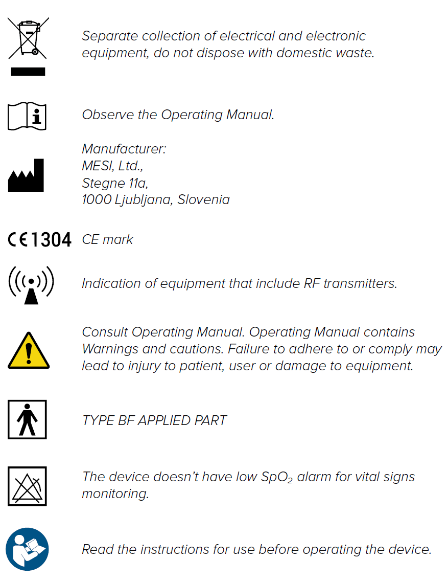
Important labels